• Learn to make fully
    3d printable designs
  • Fusion 360
    Beginners Tutorial for 3D Printing

    Overview

    The aim of this Fusion tutorial is to show you how to design parts for 3D printing in Autodesk Fusion 360, from scratch. Fusion 360 is very versatile and so there are more than a few ways to achieve what you want. We’ll cover the most relevant method for each task in this guide.

    The object we are going to create is a shelving bracket. I know, it’s a boring choice of an object, but it nicely demonstrates some basic design concepts used in its construction making this one great example of many beginner 3D printer projects.

    Looking for a Udemy Fusion 360 course? We’ve packed so much into this guide it’s more like a mini-course, you’ll gain more from this free guide than most paid courses.

    In this comprehensive guide you will get a working appreciation of the Fusion 360 design environment, how easy it is to use, and a complete overview of how to design 3d models for printing, taking into account design considerations and limitations for 3D printers. Something you won’t get simply learning how to create a standard 3D model.

    This article also explains that while 3D-printed objects are not usually great at handling loads, with a bit of thought about the design structure and careful filament selection, you can often fabricate an object that will easily perform the required task.

    Requirements. Things you will need…

    • To download and install the Autodesk Fusion 360 CAD package. It’s free if you’re a hobbyist, student or small business.
      More information on the available Fusion 360 options can be found on the Fusion 360 product page
    • Some paper to sketch on and something to draw with (Optional). Grid paper is really useful here. It’s a useful skill to learn being able to do your own 2D drawings to 3D model converision.
    • And if you are actually going to make this, a 3D printer (or at least access to one) would really help too.

    Objective – To take an idea and make it Real using Fusion 360 and 3D Printing

    This guide will cover:

    • What is Fusion 360, and how does it differ from other CAD environments?
    • Basic Fusion 360 interface use
    • Saving yourself from (more) grey hairs
    • Starting your design
    • Transferring your paper sketch to the “Model” workspace
    • A quick word about “Constraints.” What are they, and how to use and abuse them to get what you want.
    • Taking your drawing into the 3D Realm
    • Explanation of the Timeline Feature
    • Remodelling parts of your drawing to obtain the features you want
    • Sketching more 2D onto your 3D object, then making that 3D too
    • Making it look pretty & practical – Fillets, Chamfers and other 3D modelling tools.
    • Then how to make your STL file for 3D printing.
    • Don’t forget to save and always, ALWAYS, export and save locally!

    What is Fusion 360, and how does it differ from other CAD environments?

    There is ‘traditional’ CAD – where a flat drawing (using just the X and Y axes) can represent a layout of something on a 2D plane, but by using a technique called ‘projection’, you can also represent a 3D one, where the features of the Z axis are also represented by another 2D drawing. So it is still a flat (2D) drawing, but it only describes the Z axis of a 3D object.

    3D CAD starts out the same for the X and Y axes, but instead of just describing the features of the Z axis of the object, the 2D drawing is then ‘extruded’ out of the 2D plane along the Z axis to make an object that can be rotated in “3D space”.

    Using the computer to rotate the object, you can see a complete representation of how the object will look after you have printed it.

    Where Fusion 360 differs from most other CAD packages, is that it allows you to switch seamlessly between the 2D and 3D realms as required.

    It is also described as being “Cloud-based.” It is to some extent, but can be run ‘offline’ for an extended period with some limitations.

    Fusion 360 Ultimate is currently free to use for students and teachers, hobbyists, and business startups (that are “making less than $100K per year”).

    Basic Fusion 360 interface use

    A Quick Tour…

    There are an ever-increasing number of these as new features are constantly being added. This is the list at the time of writing:

    • Model” – At its simplest, it is used to produce 2D geometric “Sketches” and 3D extruded solid
    • Objects” – We will only be using the Model workspace for the purposes this tutorial
    • Patch” – Used for creating and manipulating bodies as well as repairing surfaces
    • Sheet Metal” – used for creating sheet metal designs
    • Render” – is used to make a design look more realistic by adding colours and textures
    • Animation” – used for creating animations of how the design should be operated or assembled
    • Simulation” – performs simulations of the part in use, showing possible points of stress failure
    • CAM” – generates toolpaths for CNC manufacturing (CAM = Computer-Aided Manufacturing)
    • Drawing” – is used to create engineering drawings from your design or animation
    Figure 1: Workspaces

    The Toolbar

    Has a set of buttons specific to each workspace you are in. There too many to go through here at this time.
    Thankfully, each button has an icon that pictorially hints at its purpose. If you hover your mouse pointer over one a reminder label pops up, followed by some usage hints a couple of seconds later.

    Figure 2: An example of Hint text

    Please do not be concerned if your Panel does not look the same as the one in this tutorial, the Panel is customisable and you can add and remove most icons at will.

    It is beyond the scope of this simple tutorial to go into details, but if you cannot find what you want, each section on the Panel has a title at the bottom with a down arrow just to the right of it. Just click on the name, a menu will open, and you will find what need in there.

    The Data Panel

    The Data Panel is where all of your designs are saved and organised.
    The icon below is what you use to get access to them:

    Figure 3: An example of what you will find in the Data Panel

    The Navigation Bar (View Control)

    At the bottom of the Fusion 360 window, you can see some further icons. These change how the Fusion 360 desktop is laid out and how the objects within it are displayed. They do not affect your drawing, so play around with them (once you have something to look at) to see what is best for the task you are doing.

    Figure 4: What you can find under one of these icons

    The Browser rollup and basics of use

    If you look in the Fusion 360 workspace, you will see a little section called the “Browser.”

    This little area contains a lot of useful information. Sadly once again, there is so much information in here that it would take too long to go through in turn, but we will explain to you what you need to go as we proceed.

    As your drawing/object progresses, the Sketches and Objects you create, along with other information will be listed in the Browser.

    Figure 5: A new Browser list will look like this (expanded view)

    The basics are:

    • That by clicking a lightbulb, you can turn a feature (or a group of features) on and off.
    • In some cases, if you click one of the little icons in that tree, you can edit the values of that object directly.
    • For some objects, right-clicking on an object may bring up an associated edit menu.
    • Double-clicking may open the object for editing.
    • If the name of an object is editable, the first click on the name will highlight it, the second click (after a small pause) will then open it for editing.
      [you will do this later to change the name of the default name of your bracket]

    Mouse functions

    These are pretty much windows standard:-

    • Left-click to select (referred to as “click” from now on).
    • Double left-click to activate (“double click”)
    • Right-click for a context-sensitive menu
    • Centre (scroll) wheel for scrolling and zooming, etc. (changeable in the Settings Menu)

    BUT Fusion 360 has another feature up its sleeve…

    Mouse gestures

    If you right-click a blank area on the Fusion 360 work area, a context-sensitive menu pops up, but you will also see a circle of buttons clustered around the mouse pointer.

    Figure 6: Mouse Gesture shading

    You can move the mouse and click on any of these buttons as you need them. HOWEVER, without clicking on any of the buttons, move the mouse around the circle of buttons, you will see that a segment of the work desktop lights up behind each button as you do so.

    The truly cool part is that after you become familiar with this, you will know what buttons sit at what position. For instance, delete in (in the image to the left) sits at roughly the 10 (or 11) o’clock position.

    To get to the delete button WITHOUT having to right-click and find the button, just right-click a blank space, hold the button down, and drag the mouse pointer in the rough direction where you know the button to be, and then about as much again.

    A line will be temporarily drawn on the workspace.

    When you release the button, the selected hidden function will be executed and will take you straight to the Delete box.

    Figure 7: The Delete box

    If you mess up, don’t panic – the UNDO function sits at the 9 o’clock position, just right-click, hold the button, and drag left.

    Failing that, you can always hold down the Ctrl key and tap the “Z” key, or use the Undo arrow (left-facing one) on the top bar of the program.

    The Timeline

    This is the area at the bottom of the workspace that records the Parametric Design operations that you have carried out as your design progresses:

    Figure 8: The Timeline

    This shows that there are three operations so far in this timeline:

    1. A 2D Sketch was drawn – you can see the outline of the 2D rectangle at the bottom.
    2. An extrusion was made – the area inside the square was extruded along the Z axis to produce a 3D cuboid object.
    3. A chamfer operation was then performed – to take the uppermost edges off.
    You can use the controls on the left to move through the operation recordings.

    You can also drag the vertical History Bar to the point of interest to temporarily hide operations that come after it and change the editing point in the design.

    Figure 9: History Bar

    Double clicking on an recorded operation icon will make it active for editing. You can also do other operations by right-clicking on the operation icons to select other context-sensitive functions such as hiding these operations using the “Suppress Features” option.

    Figure 10: Timeline feature edit menu

    The Suppress Features command allows you to temporarily hide a process in the timeline to make it easier to see what is going on.
    [Note that if a feature later on in the Timeline relies on the suppressed one, that will ALSO be suppressed]

    Handy shortcuts

    There are a lot of built-in shortcuts in Fusion 360. All you need to do is look at a menu listing and see if one is available.

    If you want to see if an icon has a shortcut, hover the mouse over it.

    Here are a few useful ones to get you started:

    • Ctrl-Z for undo – vital when you make a mistake in the 2D “Linear Design” space as it does not record the same events as in the 3D one along the Timeline.
    • Ctrl-F6 is a quick way to centre and expand the current drawing or object to fill the workspace.
    • To quickly start a drawing a line, type “L” or “l” (invokes the Line tool)
    • To trim a line, type “T” or “t” (invokes the Trim tool)
    • The Delete key (Del) will delete whatever is highlighted as long as it is a valid operation
    • The Extrude tool shortcut is “E” or “e
    • A Center Diameter Circle is “C” or “c

    Don’t try to learn them all at once, pick them up as you go – it’s much easier.

    Settings – what to change and why

    There are a few settings that you might want to change, it’s all personal preferences, but one that drives me nuts when I am drawing is the “Auto look at sketch” option.

    When you are drawing something awkward, and you have the drawing set at an angle in the viewport so that you can see all aspects, it can be really unhelpful when the view suddenly swings around to look at what you just drew and destroys how you were previously looking at it!

    Here are my settings. Choose your own. Make Fusion 360 work the way you want!

    Figure 11: General Design preferences example

    [Settings can be found under your name at the top of Fusion 360, in Preferences. “Auto look at sketch” is located under: General > Design should you wish to turn it off]

    Saving yourself from (more) grey hairs

    Saving and Manual Versioning

    Saving

    When you start a new project, you want to give it a name. Initially the name displayed on the tab will be “Untitled*”until you do so.

    Click on the ‘Floppy Disk’ icon (seen in the following image):


    Figure 12: Save icon

    You will then be presented with a dialog box for you to enter a name for your new project. (I personally find that entering a short descriptive name with a numerical double digit trailing number allows you to easily chart versions you manually create)

    Figure 13: The Save dialog box

    Periodic Saving – and Labelling those saves!

    When you make any save, even the initial one, Fusion 360 tags a version number on the end of your file (v0, v1, v2…).

    As with the initial save, future saves are initiated by clicking on the Disk icon.

    Figure 14: Practical Version Labelling

    Here is an example of a mid-design save dialog box.

     You don’t have to be so specific; it’s whatever you find useful to you. 

    I usually save at a major design change.

    The information you enter here will show up in the Data Panel listing when you click on the Version box.

    The red box shows where you click to get to all the versions you have saved so far (v0, v1, v2…), and the red rounded box is to shows the icon that appears when you hover your mouse anywhere over the version information.

    Clicking on the folder will open the version in another tab so you can edit it there.

    [There are other functions in this menu such as “Promote” which changes the order so that you can make a different version the preferred one when opening the file at a later time]

    Figure 15: Inside the hidden Version number

    Making saves is good practice when you change things. You might find yourself mid-design and decide that you do not like the way the design is developing. Instead of scrapping all you have done so far, save it with a different name, then roll back the changes on the newly saved design, and proceed with the modifications.

    Figure 16: A project with unsaved changes

    This screen capture  shows the name in the tab as “Bracket01 v1*”. 

    The star/asterisk indicates that the design has been edited since the last save.

    Make manual multiple saved versions

    Making an extra save with a different name is also good practice.

    As with above, you might find yourself mid-design and decide that you do not like the way the design is developing, and so on… Instead of scrapping all you have done so far, save it with a different name, then roll back the changes on the newly saved design, and proceed with the modifications.

    If they do not work out, you will not have to delete them and redo them from the point of the original save, as you have that previous version you can go back to and continue on from there.

    This method also makes it easy to have several finished solutions that could have all branched off the same original project at differing points in the timeline, and so again, you have lost none of the work if something goes wrong, but…

    More importantly, there’s the mitigation of the old favourites such as file corruption, crashes, and accidental deletion, that this approach takes.

    With complex drawings, it is a good idea to keep a record of what changes each version incorporates in a log book. Like the good practise of making frequent backups of your work, it’s also good practise to start keeping a log before you need it. The more complex your projects get, the more you will need it in the future.

    Useful things to record are –

    • Project name and date
    • Requirements
    • Measurements and calculations
    • What you did and why you did it
    • Mistakes/errors made previously
    • Problems
    • Compromises
    • Anything else you might want to refer to

    Why?

    You will be lucky if you remember all of these details tomorrow, let alone a week from now and notes on saves can only contain so much information…

    The importance of LOCAL saves!!

    “Ooh, it’s safe in The Cloud.” Rubbish!!

    ‘The Cloud’ is just someone else’s computer storage. It can get switched off or the data could be deleted and therefore lost at any time.

    While we are at it, just how much are you paying Autodesk to keep copies of your data safe?

    Nothing? Thought so.

    So, ask yourself – Is your design data and hard work worth so little that you are relying on someone else to keep it safe – for free?

    In over a year of using Fusion 360, I have never suffered a loss of a file from the Autodesk servers for any reason, but there is always a first time.

    So for your own sanity, please keep Local Backups!!

    Starting Your Design

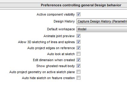
    Now all that admin is out of the way, it is time to begin with actually how to design your 3D printed parts.

    First, measure and make written notes of your shelving requirements:

    • The material
    • Dimensions
    • An estimate of how much weight bracket needs to support right now (and in the future as use-cases often change).
      Don’t forget to include the weight of the shelving into this estimate.

    Try to get a feel of how strong the filament you want to use is, and whether or not it will stand up to the load. For instance –

    • PLA is a fantastic modelling plastic, but it will distort and bend under heavy loads, and this gets significantly worse as the temperature rises. If you have a shelf over a radiator or in direct sunlight, the shelf is not going to last long at all.
    • ABS will likely do what you want, but it is difficult to print successfully without an enclosed and heated chamber.
    • rigid.ink’s Carbonyte would be an outstanding choice for use as a shelf bracket as it is incredibly strong, but it is relatively expensive and as such may a bit of an overkill for all but the most demanding of brackets. It also has the issue that it may require an enclosed chamber in order to get the best results.
    • A good compromise is rigid.ink’s PETG. You have good overall strength, superb layer bonding, and you do not need a chamber, heated or otherwise, in order to be able to achieve perfect results.

    You can see a handy table of the relative strengths of rigid.ink filaments in the rigid.ink Filament Comparison Guide along with other useful information.

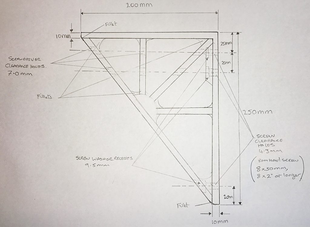
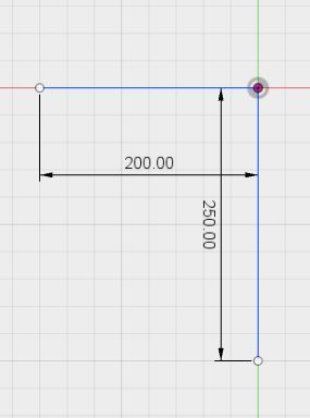
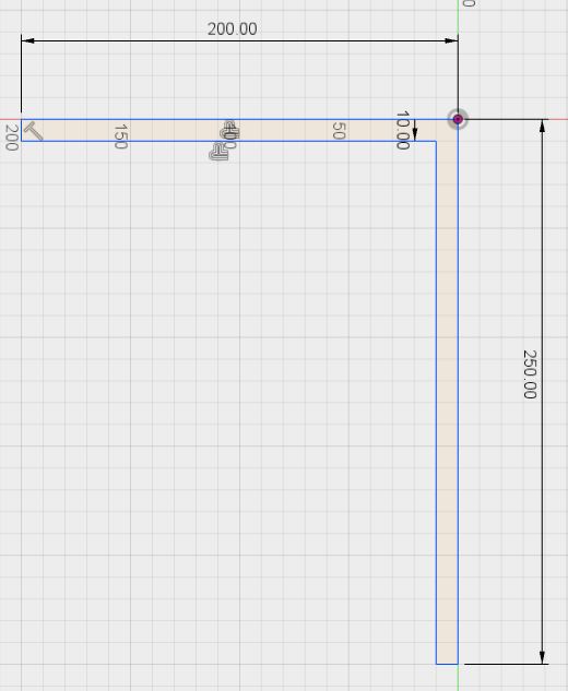
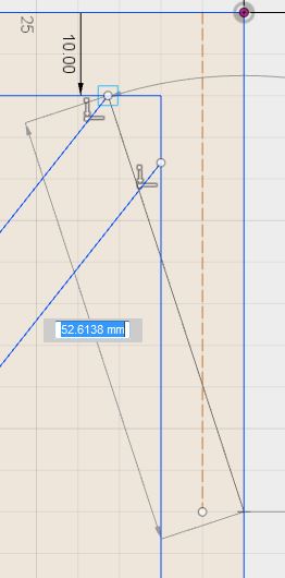
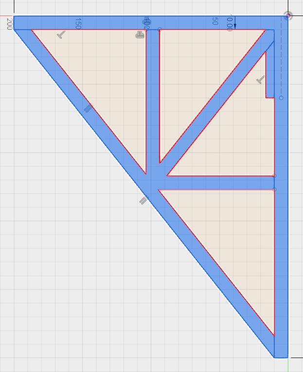
    Take a piece of paper and draw out a representation of the top of the bracket and how far it will come down the wall (graph paper can help with this if you are having difficulties).

    It does not need to be to scale. As long as you can understand what you have drawn, then that is fine.

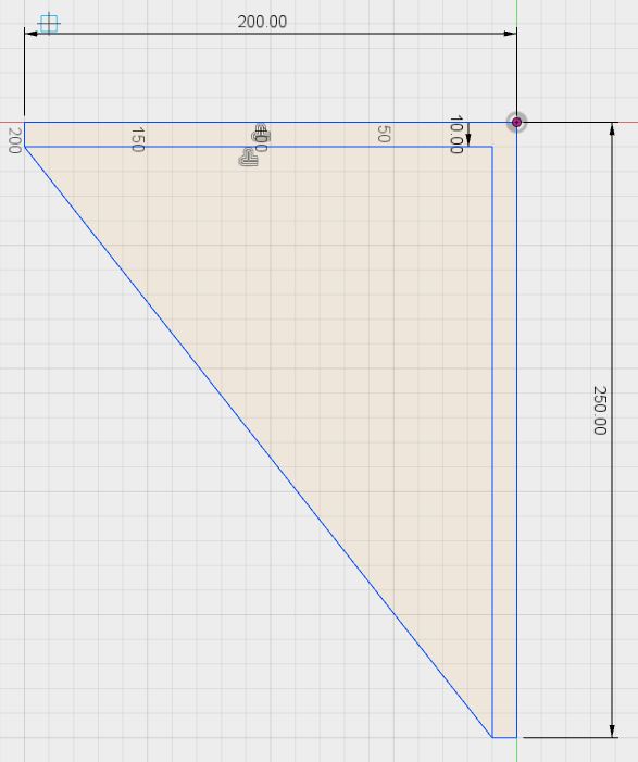
    For lightweight shelving, you can sometimes get away with a bracket that has equal length arms, but this is not recommended.

    This is because you want the wall fixings to be in what is known as ‘shear’, rather than /tension’.
    ‘Shear’ is where the shelving weight is concentrated such that the forces are arranged so that the load is vertically down the wall (trying to shear-off the fixings), rather than trying to pull the fixings out of the wall by placing them under ‘tension’.

    Basically, if the wall section is too short, you have a lever action that is really good at pulling fixings out of the wall by increasing the tension at the top of the bracket using the lowest part of the shelf as a fulcrum (pivot). This is why the long edges of a bracket should always be fixed to the wall and not the shelf to obtain the best shelf load-carrying.

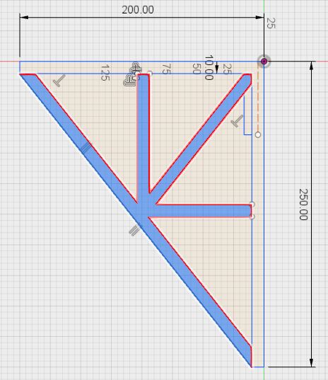
    A good minimum difference is where the wall length is about 120% of the shelf width – so a 25cm shelf bracket would have a wall section of 30cm (or greater, depending on design load).

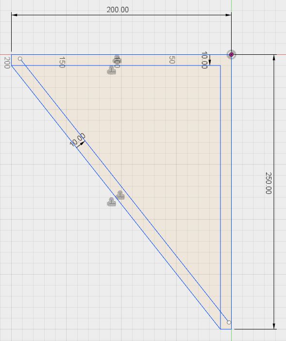
    Your drawing also needs to take into account what plastic you are going to use (as said earlier, PLA is *NOT* a good choice!), and how thick the plastic bracket is going to need to be.

    Details that might not have been previously considered, like material choice is also an important element when working out how to make a 3D model from a picture or drawing.

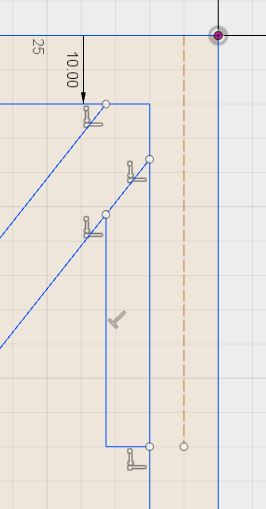
    For a ‘normal’ 25cm shelf bracket, I would suggest that going below 10mm with PETG being used as the printing material is probably asking for trouble for all but the lightest of shelves. Add this dimension to your drawing.

    The width of your shelf will also be a factor you will need to consider.

    Always remember, different filaments will have different requirements. With super-strong materials such as rigid.ink’s Carbonyte, it is quite possible to reduce the thickness of the bracket with very little loss of strength.

    Lastly, don’t forget to roughly assign where you want the screws to go.

    Remember, the drawing does not need to be perfect, just as long as you get the basic idea down of what you want – as you can see in the drawing below:

    Figure 17: A preliminary sketch of the requirement often helps

    Transferring your paper sketch to the “Model” workspace

    Now you have your drawing sketched out on paper, it is time to start creating your design for 3D printing in Fusion 360.

    Open Fusion 360 and ‘Save’ the “Untitled*” page with the name of your project in the location of your choice

    Ensure you are in the “Model workspace”. (see image below)

    Figure 18: This shows the Model workspace is selected

    Now to set up your workspace so we are in sync

    To switch the current view to drawing in the XY plane, click “Top” on the cube.
    (Note: you do not have to do this, as you can start a drawing using the icon and click on any plane you wish to draw on – it just makes life easier for the purpose of this project instruction)

    By clicking Top, you have arranged the drawing environment so that it now looks similar to what you would see if you were to look down on your printer bed from directly above.

    Assuming you stood at the front of your printer the Y-axis goes from close to you to far away, the X-axis goes from left to right, and the Z-axis comes straight out of the bed vertically towards your viewpoint. 

    The ViewCube will now look like this:

    Figure 19: ViewCube from the Top

    You can use any of the arrow keys or surfaces to rotate the cube (and so the view), all except the one on the bottom right, as this is used to select other view types and change the settings.

    The little ‘house’ icon in the top-right corner returns the cube to the original set ‘Home Position.’

    Let’s start making your bracket

    Create a new Sketch by either clicking the highlighted icon, or by clicking on the word “SKETCH” itself.

    Figure 20: Click the Sketch icon or “SKETCH” to start

    This second method opens a menu with an item, “Create Sketch.” This just opens a blank Sketch the same as the Panel icon.

    Selecting one of the other items, providing it is not greyed-out, will auto-create a Sketch with selected function activated.

    You are then presented with a workspace that has this image in the middle of the screen. This shows the three planes and the axes; X (red), Y (green), Z (blue) in the space where you will be creating your object:

    Figure 21 016 OriginBulbOn - Copy
    Figure 21: Axes and drawing planes

    In case you are worried you will get lost and/or never remember the colours, on the top-right of the Fusion 360 desktop, you will see a tilted ViewCube that shows the coloured and labelled axes.

    Figure 22 005 CubeToolDefault - Copy
    Figure 22: The ViewCube

    You can ‘grab’ (left-click&hold) any part of the ViewCube at any time in the 2D or 3D realms during your design process, and use it to rotate your viewpoint to one that better suits you.

    Clicking on any of the faces, facets, or corners, will auto-rotate your object drawing or object to those predefined views. These can be very useful.

    If you clicked on the “Top” face of the ViewCube, you will now be presented with an open Sketch, and in the centre there will be a square that looks like this:

    Figure 23 026 SketchXYplane - Copy
    Figure 23: X and Y axes with the XY plane (grey)

    As mentioned earlier, the green line represents the Y-axis (which is front to back on most printers), and the red line represents the X-axis (left to right).

    Where the X and Y lines meet (the small circle with a dot in it) is called the ‘Origin.’ This is where a the Z-axis is also anchored, but as we are only drawing in two dimensions (X & Y) at the moment, the Z-axis is hidden from view.

    The grey square represents a ‘Plane.’ A plane is something you draw on. There three basic starting planes in 2D drawing – XY, XZ, and YZ. Each is placed at 90 degrees to each other, and intersect at a single common point – the aforementioned Origin.

    You can define custom planes later on, but these are the ones that all drawings and objects spring from.

    Click on this square to select the XY-plane as this is the one you will be drawing on. The Origin of the Sketch will now look like this:

    Figure 24 027 SketchXYorigin - Copy
    Figure 24: The Origin

    Confirm this for yourself. Grab the ViewCube and rotate it around to see that the Z-axis is hidden.
    To get back to the view we had above, click the ‘Home’ icon, then on the side labelled “Top.”

    Figure 25: The ViewCube should look like this again

    To close a Sketch at any time, just click on the “Stop Sketch” button on the far-right of the Panel as seen here:

    Figure 26: The Stop Sketch icon

    NOTE: The STOP SKETCH button does NOT appear until you actually start drawing! So please do not worry.

    Getting your drawing into a Fusion 360’s Sketch

    Look at your hand-drawn sketch, and note the length of the line of the part of the bracket that goes against the wall (in this article’s drawing, it is 250mm).

    Find and click the Line tool:

    Figure 27: The Line tool

    Place the mouse cursor over the Origin and click on it to anchor the line at this point.

    Drag the mouse downwards, making sure that the line is vertical (90°).

    You can either keep moving the mouse to get the right length and then click the mouse to mark that point, or as is much easier (in this case), just make sure that the line is still vertical (90°), let go of the mouse, and type in 250. Press the Enter key on the keyboard.

    Not only will it set the line at the correct length, it will dimension it for you automatically.

    If you had clicked at the correct length, the line would be anchored there (with no dimensioning visible), and the Line tool would still be active so that you can daisy-chain your line drawing process.
    [You can always add dimensioning later with the Dimension tool]

    If all went well, it should look like this:

    Figure 28: The first Line – the back of the bracket

    If it does not, click the left facing arrow until you get back to the view shown in Figure 24, and start the process again.
    [You can also use the key combination of Ctrl-Z to undo errors. Multiple presses = multiple undo operations]

    Once you have completed this, then click on the Line tool icon again to invoke it, OR, you can use the Shortcut KeyL” to speed things up.
    [Lower-case l also works].

    Now draw the 2nd line of the bracket leftwards from the Origin (now showing as a red dot with a circle around it) until the line sits horizontally (180°), enter the value 200, and press Enter. It should now look like this:

    Figure 29: The second line – the top of the bracket

    Note at the ends of the two lines there are small circles. These are called ‘Sketch Points’. They have multiple functions, but for the sake of simplicity, we will just use them as a point to draw from later on

    You now have the basic outline dimensions of the bracket entered into your Fusion 360 Sketch.

    If you are happy with this, click the Save icon (floppy disk), enter a description (or not, your choice), and click ‘OK’, or press Enter.

    Figure 30 30 SketchIn-Drawing1stSave - Copy
    Figure 30: Giving the version save a useful name

    We don’t want to have to mess about drawing in all the lines, so there are a few shortcuts we can take, and once again, this is where Fusion 360 excels!

    For a start, to get your drawing maximised and centred in the Sketch viewport, press the “F6” key on your keyboard.

    This is not perfect a perfect procedure, but it reduces all the zooming and translating that can be so tiresome when trying to locate something in the viewport.

    It also works the same in the 3D realm.

    What we want to do next is to enter the surfaces that are parallel to those already entered, but at a set distance. For this size bracket, it needs to be about 10mm for heavy loads.

    To put these lines in easily, we use the “Offset tool” (Shortcut Key “O”) seen highlighted below:

    Figure 31: The Offset tool and Hint text box

    Click on this icon and you will get a dialog box:

    Figure 32: The Offset tool dialog box

    Click on one line on the Sketch, and you will see them both go darker. A red line will appear next to them – this is the offset lines.

    If this only happens to one line, check that the “Chain Selection” box is ticked. Otherwise you will need to select each in turn.

    Figure 33: The Offset tool at work

    You may notice at this point that the offset has been created on the sides opposite to that which you want. This is easily fixed.

    If you look at the Offset tool dialog box, you will see this icon:

    Clicking this will flip the direction of the offset.

    Figure 34: Invert Offset direction button

    Your sketch should now look similar to the one below:

    Figure 35: A 10mm offset

    Click OK/Enter to finalise. Ctrl-Z, etc., to undo.

    Left-Click&Hold the dimension values and drag them out of the way in order to make the Sketch look a bit tidier:

    Figure 36: A neater view

    Now, using the Line tool, click on one of the two Sketch Points that are close together and start a new line. Click on the nearest Sketch point and the line will terminate.

    If it does not terminate and the line wants to draw some more, then you have missed the Sketch Point that will seal that end of the bracket.

    Just Undo what you did, and try again.

    Do the same again with the other pair of Sketch Points and you will see that you have created a closed (also known as ‘manifold’) shape within the 2D realm of the Sketch.

    To indicate that this is now a closed shape that is capable of being ‘extruded’ into the 3D realm, it has become shaded:

    Figure 37: A ‘Closed’ or 'Manifold' shape

    If the shape did not close, use the mouse scroll-wheel to zoom in and check BOTH ends of the small lines to see that the really are connected together.

    If not, the easiest way at this stage is to click on the offending line so that it is highlighted and tap the del/Delete key so that you can redraw it.

    Assuming that you are now happy with your closed shape, place the cross-hair cursor over the top-left lower-corner of the now closed shape, and it will change to look like this:

    Figure 38: A selected Vertex

    Click on that corner, and drag the line to the opposite corner and this will now close the triangular section (note the shading of the successfully closed shape) so that it looks like this:

    Figure 39: The closed outline of the bracket

    Activate the Offset tool (“O”). Click on the longest edge of the bracket and click the down arrow until -10mm is showing. Click OK/Enter:

    Figure 40: Another 10mm line offset

    Next, locate the Trim tool [Shortcut is “T” or “t”]. If it is not on your Panel, you can find it in the Sketch drop-down menu.

    It looks like this in either location:

    Figure 41 153 Trim tool HL
    Figure 41: The Trim tool icon

    Hover the mouse over one of the loose ends of the Offset line you just created, and it will turn red.

    Figure 42: First Trim

    Click the mouse on the red part to delete.

    Repeat for the other loose end.

    Press the Escape key to cancel the Trim tool mode.

    Now might be a good time to save your work.

    Figure 43: Second Trim

    Making the support spokes

    There are all sorts of engineering mathematics that goes into working out the stresses involved in making proper supports, but this is once again outside of the scope of this tutorial.

    So here’s the ultra-quick and dirty method to produce a spoked cantilever support using features of Fusion 360.


    Select the Line tool by your preferred method.

    Move the crosshairs down the inner line on the longest side of the bracket until a small triangle icon appears next to the cursor location – the is the midpoint icon of a line.

    Figure 44: Selecting the centre line

    Click on this location to start a line. Terminate the line in the INNER top right-hand corner of the bracket.

    Start another from the same mid-point, and go vertically up to the inner wall, and then from the same point to the inner vertical wall, so you get this:

    Figure 45: The spokes of the support

    Click the vertical line, then hold down the Ctrl key and click the horizontal line. Both should be highlighted.

    Use the Offset tool to create a L-shape 5mm one side of those lines like this:

    Figure 46: Making one side of two spokes using the Offset tool

    Repeat, but make the L-shape 5mm to the other side. Don’t forget to use the invert direction button on the Offset tool dialog box to make this happen.

    Now select the line (only) that goes to the top-right corner and repeat for a line 5mm either side of the original.

    Once done, you will get the following drawing:

    Figure 47: The basis of the spokes

    Use the Trim tool (Figure 41) to remove the non-essential lines.

    [You do not really need to do this with such a simple Sketch, but it can cause problems with complex drawings. These loose ends can combine with other lines to make ‘pockets’ of shapes within your Sketch. These can then easily be missed when extruding a sketch and so corrupt the surface of your object. It also looks messy]

    When you are finished, you are left with this:

    Figure 48: After tidying with the Trim tool

    This might be a good time to save and create a Manual Version for a bit of practice…

    Click on the File icon and select “Save as” from the drop-down menu.

    Figure 49: The File icon, and “Save as”

    Remove the V-numbers that Fusion 360 has added and increment your document number.

    Example change “Bracket01 v6” to Bracket02” and press the Save button to complete.

    NOTE: This protects your older version from accidental damage, but you do lose all of the ‘Undo Points’ up to this Save so make sure you are happy with what you have.

    It’s time now to consider the reinforcing for the screw mounting holes:

    All of the lines we have done so far are for the actual profile of the bracket.

    There is another kind of line that is not counted as being part of the actual object – the dashed construction line. It is handy for guidance, setting up distances and positions of extrudable features, and so much more.

    We are going to use it here to set the location of the screw reinforcement at the top of the bracket.

    Select the Line tool.

    Draw a line downwards from the uppermost line at 90 degrees from a point 5mm in from the edge of the bracket closet to the wall (on this grid, 1 square is 5mm x 5mm).

    Make it 60mm long.

    Highlight by clicking on it, the press the ‘X’ key and the line will become dashed (as seen below) and is now non-extrudable (pressing X again reverts the line type):

    Figure 50 55 SketchConstructionX - Copy
    Figure 50: Change a solid Construction line to a dashed one

    Delete or move the dimension of this line out of the way (that is the 60mm info – just click on it and press the Delete key).

    Select the Line tool again, and hover the pointer over the Sketch Point at the bottom of the line, and then move it towards the vertical line on the right.

    A blue dashed line will follow the cursor at 90 degrees as you move away from the Sketch point.

    When it intersects the vertical line, the crosshairs become a blue X with a box around it.

    Click this point, and this will become the line start point.

    Figure 51: Aligning one point to another

    When the line starts, hover the mouse pointer over the point in the following point. Do NOT click the mouse! Just the act of doing this creates a temporary alignment link with this point or this will happen:

    Figure 52: Hover the mouse over the point, do NOT click it!

    [You could do this way, but I am trying to show you that you can have multiple alignment points in play at the same time]

    Then, while keeping the mouse vertically in line with that point, move the mouse down the screen until the line from the first point is perfectly horizontal. If you are in the right position, there will now be blue dotted lines that intercept the mouse pointer horizontally AND vertically:

    Figure 53: TWO alignment reference

    Click the mouse at this intersection point (the blue X)and draw a line that meets the vertical line like this:

    Figure 54: Click and draw the line to meet the vertical

    Now go back to the beginning of the line, click and move the pointer back over the top Sketch Point so that the blue dashed line appears again.

    Move the mouse cursor to the point where it crosses the lower of the two diagonals:

    Figure 55: Intersecting the diagonal while using an alignment

    When you are certain that the cursor intersects the diagonal, click the mouse button to get this:

    Figure 56: The completed reinforcin

    To make sure you have drawn a closed shape, click in the middle of the shape and it will now look like this:

    Figure 57: The shape is closed

    If it does not look like this, you have more than likely missed hitting the diagonal line. Zoom in and have a look. If you have, select and Delete it (or use the Trim tool if you like) then have another try.

    So this is the final first Sketch. (Save and Manual Version if you want to):

    Figure 58: The final Sketch

    It is worth noting at this point that there are other lines that could have been removed using the Trim tool as the Spokes and the Top and Back are all going to be the same extruded height.

    Leaving those lines gives the flexibility that the spokes can be a different height if you decide to make a change later.

    With such a simple Sketch it does not really increase complexity to leave them in.

    Taking your drawing into the 3D Realm

    Now it’s time to leave the 2D Realm behind and move into the 3D Realm one by extruding your drawing into the Z-axis (remember, until now we were drawing the features we wanted on the XY plane).

    “Manifold” Objects

    There are a few definitions for the word “manifold” kicking around, but the one that refers most when you’re looking to learn 3D printing design is the one that addresses surface integrity – whether the surface has any holes in it.

    The easiest way I have found to describe this to use an inflated football as an example.

    The inflated ball is an example of a ‘manifold object’ (as long as there are no leaks!).

    The ball has TWO surfaces – the inside and the outside. 

    Now, if you make a hole in the ball, the inside effectively becomes connected to the outside, and if you ignore the thickness of the ball skin, you effectively only have one surface.

    It still looks ball-shaped from a distance, but close-up examination shows it is no longer a ball. It has become a single surface of infinite thinness – it is a mathematical anomaly that Slicing software does not like and so is to be avoided.

    In CAD, if you have something that is shaped like this –  Ↄ, it cannot be extruded to produce a solid object, but this – D can as there is an enclosed area inside the object. You have to have a fully enclosed area for it to be extruded. Like the ball, the inside of the D is isolated from the outside.

    As seen earlier, as you draw in Fusion 360 and parts become manifold, the area enclosed by the lines changes color. It gets darker:

    Figure 59: Manifold shapes

    Clicking on any darkened area (inside or outside of Sketch) will show all linked areas to it that are part of the same enclosed space:

    Figure 60: Complex shapes can be manifold

    To select ALL the part you want to extrude, hold down the Ctrl key, and select the three separate sections of the of the body of the bracket so that it looks like the image below:

    Figure 61: Select the parts you want to extrude

    Click on the Extrude tool (Shortcut Key “E”):

    Figure 62: Select the Extrude tool

    Either grab the blue arrow with the mouse button and pull it in the direction of the arrow until the Distance box shows 30.00 mm, or just type 30 into the box.

    Press OK when you are ready.

    Figure 63: Enter 30mm in the Distance box

    If all went well, your object should now look like this:

    Figure 64: The bracket Sketch is now an object

    If it does not, just use the Undo function (Ctrl-Z) to step backwards, and redo it.

    Hurray! You now have, in a very basic form created a model that could be 3D printed. But as it is, it wouldn’t be a very useful print, so we’re not finished yet.

    Once you are happy with this, if you take the time to look at the bottom of the Fusion 360 workspace, you will see that the Timeline now has TWO operations recorded on it:

    Figure 65: Two operations recorded on the Timeline

    The first icon is from when you created your Sketch, and the second is from this extrusion.

    Each time you create something that affects the 3D Realm, another record (icon) will be placed here (unless you turn recording off).

    Each recorded operation can be revisited and edited at a later date.

    You should know that changes you make here, will ripple up through the timeline to affect your later design operations.

    Some may totally invalidate later operations and so they will need updating/fixing or even deleting.

    This ability to ‘go back in time’ is what makes Parametric CAD so powerful as you do not have to redraw your whole design if you find that you need to change things at a later time.

    Drawing the mounting screw positions

    This design needs holes for mounting onto a wall or other vertical surface, and possibly holes to allow fixing screws for shelf materials.

    We are only going to cover the wall-mounting screw holes here as they are more complex than the shelf holes. Also, any holes that this design puts in, might not be in the right place for you.

    All you need to do is follow the first few stages of this next part of the design to get what you need for fixing a shelf to the bracket.

    Rotate the ViewCube until it looks like this:

    [Hint, click on the Home icon, then in the centre of the “RIGHT” face, then the curved arrow that points left]

    Figure 66: Rotated ViewCube

    You should now see the (longer) back of the bracket as shown below:

    Figure 67: The back face of the bracket

    We could place a new Sketch directly on this surface, but this means that the Sketch will be physically tied to the surface.

    If you want to change things at a later date, or make other unconnected objects that that might be in close proximity using the same drawing, it can make things more awkward than they need to be.

    There other good reasons too, but they are outside of the scope of this tutorial. Suffice to say, it is good practise to use an Offset Plane to draw on instead.

    Getting into the habit of using them now will save you much frustration in the future.

    [Note: An Offset Plane with an offset of 0.00mm works EXACTLY the same as if you are drawing directly onto the 3D object surface, but gives you more flexibility later if needed]

    Below, is the Offset Plane tool. Click on it and the following popup is displayed:

    Figure 68: The Offset Plane too

    As you can see, the “Select” button is highlighted. What you do now is click somewhere on the visible surface of the 3D object, and you will see something very similar to this:

    Figure 69: Setting the Offset plane value to 0.00mm

    Enter no values, and click the OK button.
    [This gives you that isolation from the physical surface of the object as mentioned above, but you are drawing in the same place]

    You will see your object in the window, but it now has a plane (light brown) on the surface facing you. [The darker part just indicates that there is an object under the plane]: 

    Figure 70: The offset plane 'surface'

    Click the Create Sketch tool, and the workspace will now change to look like this:

    Figure 71: You are being asked where to Sketch

    As you can see from the pop up, you are being asked to, “Select a plane or planar face”.

    A “plane” is what you just created. If you were drawing directly on a flat surface of the object itself, that is a “planar” face.

    As we want to be certain we are drawing on the correct plane, click on the shaded square covering the object.

    Note: On large objects, the shaded plane area will not cover the whole surface, so be careful.

    ALSO, make sure you avoid any other planes:-

    If you move your mouse pointer between the plane covering the bracket and the similar square patch at the top (this is the indicator for the YZ Plane that is extending out of the Origin), you will see the focus will jump to that instead.

    Drag the mouse back to the offset plane until it is highlighted, and click on it to make it active.

    [Remember, you can switch off the Origin planes at any time by clicking the yellow bulb icon in the Browser to hide them]

    Now take a moment to look at the Timeline at the bottom again.

    Figure 72: The Timeline is storing more operations now

    You can now see recorded: Your first Sketch, the 30mm extrusion, the 0.00mm offset plane, and the new Sketch you have just started.

    Once you start to draw on the plane, the plane will auto-hide, and the workspace will change to look like this:

    Figure 73: The offset plane is now invisible

    [Don’t worry about the plane vanishing, you can get make it visible again at any time.
    When you created the plane, a new item was added to the BROWSER named “Construction.” Just expand that item entry (click the right-arrow), and click on the ‘light bulb’ to make it visible again.
    BOTH bulbs need to be ‘lit’ in order to see the plane]

    Select the Line tool, and place it roughly over centre of the top edge of the bracket.

    When you are in the centre, you will see the midpoint indicator appear (a small blue triangle), and the crosshairs will switch to a blue X when this coincides with a congruent point you can draw from.

    Click the left mouse button to start the line.

    Figure 74: Selecting the centre point on an edge

    Move the mouse down 25mm, and click the Enter key to auto-dimension it. 

    Click on the BLUE line that you just created so that it is highlighted.

    Figure 75: Draw a 25mm line

    Press the ‘X’ key to convert it to a dashed construction line (remember – it is now no longer part of the object).

    If you look at the SKETCH PALETTE, you can see that the dashed version of the Construction has a blue/grey overlay on it showing that it active and a dashed line is selected.

    Figure 76: Dashed Construction line indicator

    To switch back to a solid construction line (other than using Undo), highlight the line again and press ‘X’ once more, or click that blue Construction icon…

    [HINT: If you need to do a lot of non-structural drawing using dashed lines, before you draw, click on the icon on the Construction icon on the Palette to lock it in that mode. Click again to unlock.]

    Re-enable the drawing tool by any method, and select the Sketch Point where the previous line finished, and make another 25mm line. Make this dashed also.

    Figure 77: Adding a second 25mm dashed line
    Figure 78: Screw hole positions are marked now (25mm, 50mm)

    Now repeat at the bottom of the bracket, but this time only come up from the bottom of the bracket, and only by 20mm.

    Figure 79: All three screw hole positions

    If you locked the line mode into the dashed one, click the Construction icon on the Sketch Palette so that it now looks like this:

    Figure 80: Solid Construction line indicator

    Select the Center Diameter Circle tool:

    Figure 81: Center Diameter Circle too

    Locate with the cursor the first screw location from the top (25mm down).

    When you get over the point (that looks like the position shown below), the cursor will change to resemble a blue square (a Sketch Point from the dashed lines we just drew):

    Figure 82: Located a dashed-line Sketch Point

    Click the point, and move your mouse in any direction and a circle will appear.

    The screws I am using have nominal diameter of 4mm., so to provide a little extra clearance as 3D printed features (especially small holes) are not that accurate, I have added an extra 0.3mm to the diameter.

    That’s 4.3mm total.

    Enter this value into the box and press Enter:

    Figure 83: Screw hole size

    [HINT: Zoom in first either by using F6, or use the mouse scroll-wheel]

    Tidy up the drawing by clicking on the value (ONLY) and drag it off to the side.
    Don’t worry if you mess it up, just Undo and try again:

    Figure 84: Move the circle dimension out of the way

    Now do the same again, but this dimension is used to provide the recess that will hold the load-spreading washer.

    I used a washer that had an outer diameter of 9mm, so a 10mm diameter here is ideal for this:

    Figure 85: Repeat with the washer clearance hole size

    If you do not tidy up the numeric values, you will end up with a mess that looks like this:

    Figure 86: What happens if you do not clear up the dimension values...

    Once tidied, they are much easier to read:

    Figure 87: Tidy dimensioning

    Now add a third circle at 7mm (the clearance holes for the screwdriver) to each of the holes.

    [You do not need to do the one located at the bottom/20mm point as this does not require a clearance hole, but I showed it here just in case you want to]

    [The dimension values look messy here as a result of my zooming out to make a smaller image]

    Figure 88: All the hole locations are now set

    Cosmetic Features – Fillets and Chamfers

    As a general rule, you should try to leave cosmetic features such as Fillets and Chamfers as late in the design sequence as possible.

    This is for many reasons, but the major one is that they can negatively affect the way surfaces can be manipulated (such as extrusion or intersection, etc.) at a later time.

    However in this case, you may need to punch a clearance hole through the curve of a fillet (depending on your settings if you make a different bracket), so we will do this now.

    Select the Fillet tool from the Toolbar:

    Figure 89: Selecting the Fillet tool

    Now click on the line formed where the left-hand (top section) inner surface meets the inner angled support (of the triangle/bracket hypotenuse):

    Figure 90: Select the inside corner intersection line

    Now do the same for these other points and your selection should look the same as the following image.

    If not, click the incorrect line again and it will be deselected. Click the ‘X’ on the line in the Fillet dialog box to clear all selections.

    [Note that you can select THROUGH the object if you can see the edges you want]

    Figure 91: The inner major corners are selected

    Enter “8” in the Radius box to set the size of the fillet and press Enter on the keyboard to accept this:

    Figure 92: How an 8mm fillet looks

    Now we need to fillet the other inner parts of the intersections.

    For the purposes of this demonstration, in order to keep this simple, we are going to select them all and make them the same size.

    [You can always select less edges and repeat the following process with different values if you wish to improve how the final design looks]

    Select the Fillet tool once again, and select the remaining internal points as seen below:

    Figure 93: Select all the other internal angle intersections

    Enter a value of “5” into the Radius dimension box:

    Figure 94: Set a 5mm Radius

    As you can see that although 5mm was a good choice for most of the angles, where the spokes met, it no longer looks all that great.

    [A good way to ‘cheat’ this is to put different values in for select lines to make it look more balanced. In reality, you would not design an intersection like this, but we are trying to keep this simple]

    We could leave the cosmetics here, but this will leave a lot of sharp edges – something that is never a good thing, especially if you have a healthy aversion to cuts like I have.

    If you print the bracket solid enough you could remove the edges post-printing, but it makes more sense to do as much as you can during the drawing process as it not only makes it safer, you can make it look much nicer by doing so.

    You will likely save plastic as well.

    There are a few things you should consider here as you will likely be using an FDM/FFF printer to be making this bracket:

    • Each printed layer needs some kind of support from the layer or layers below.
      This means that if any layer creates an overhang of less than about 45 degrees (from the horizontal print bed print plane – XY), the print may sag down. It will look awful, and have little to no structural integrity.
    • Setting a chamfer at 45 degrees or greater will stop this happening. It is inadvisable to use a fillet, as it goes from 0 degrees (flat on the bed) and then increases. It will look awful until it starts to approach the 45 degree part of the object.
    • If you are desperate to use fillets, you can mitigate some of the failings of a fillet below 45 degrees by using your slicer to print supports for it. However, these supports can give a less than pleasing finish to the filleted surfaces.
    • In other words, it is much easier to use chamfers of 45 degrees or greater where the object meets the bed.

    Select the Chamfer tool from the Toolbar:

    Figure 95 145 ChamferToolIcon - Copy
    Figure 95: The Chamfer tool icon
    Figure 96: Removing sharp edges before printing

    In order to remove the sharp edges and reduce any flaring-out of the plastic where it meets the print bed surface, we will apply a minimal chamfer to the top and back surfaces:

    This only needs to be a small amount. So enter “1” into the Distance dimension box, and press Enter:

    Figure 97: A 1mm chamfer

    As we want any edge cosmetic changes to flow nicely from the small front and bottom sections, we need to combine these two surfaces into the long diagonal ones so there is only one surface, instead of two end faces and a diagonal.

    Open the Fillet tool and select the two lines at the end of the diagonal face, as seen below:

    Figure 98: Reducing the edge count

    Enter a large value into the Fillet Radius box.

    You want it to be big enough to make the curve look nice, but not too big so as to remove too much material near the bottom end where the single screw is situated.

    Remove too much and you will not have enough room to hide the screw head when you make the washer recess.

    I suggest you enter “10” for this value at the moment. You can always change it later if it does not look right to you. Click OK or press Enter to accept:

    Figure 99: A 10mm Fillet looks nice

    Now, to tidy up those inner edges.

    Remember, that you are making it easier on yourself if you use chamfers for this than fillets.

    Open the Chamfer tool, and select all of the 10 edges. Your bracket should now look like this:

    Figure 100: Select all internal edges

    Drag the arrow until 3mm is shown in the Chamfer Distance box, or just type “3” in there and click OK/press Enter:

    Figure 101: Adding a 3mm chamfer

    Your bracket is now really beginning to take shape!

    Figure 102: The final bracket body shape

    Making the Screw Holes

    Rotate your bracket so you can see Sketch2 displayed on the back surface of the bracket.

    [If for some reason it is not visible, look in the Browser to make sure that both the “Sketches” and “Sketch2” lightbulbs are yellow. If “Sketch2” is not listed, check the Timeline to make sure you do not have the option to “Suppress Features” selected for Sketch2. It will be greyed-out if you have. Right-click and click on “Unsuppress Features” to make Sketch2 visible again]

    Open the Extrude tool (“E”) and select the centre SURFACES (not the lines) of the three screw holes:

    Figure 103: Select the 3 screw hole surfaces

    Click-hold the blue arrow, and drag it downwards until the red outlines (red denotes a “Cut”) pass through an outside all of the object.

    Or you can type in “-210” if you prefer (as long as it passes through everything, it does not matter the length):

    Figure 104: Drag those holes right through everything

    Click OK/press Enter to confirm, and your bracket will now look like this (notice the holes through the top spokes):

    Figure 105: You now have screw fixing holes!

    Extrudes with an offset (Offset Plane)

    It is now time to make the clearance holes for the screwdriver to pass through.

    Now this is where things start to get clever.

    We obviously do not want the screwdriver clearance hole to start at the plane of Sketch2 as that would remove a lot of the plastic needed to maintain the strength of the mounting points – you only need holes in the back part large enough to clear the screw shafts (4.3mm), and not huge ones at 7mm!

    So we need to tell Fusion 360 to start the recess/counterbore at a set distance from the Sketch2. This is also called an Offset Plane, but this time we are going to use a value other than 0.

    [It is similar to the Offset Plane you created earlier when drawing the sketch for the screw holes, but it is only temporary. It is temporary in that it only exists as a reference point for the start of the holes]

    Open the Extrude tool once again, but this time, select the surfaces of the circles next to the holes (that is on ALL three holes! Only the top two are shown here for clarity).

    These holes provide the clearance required for the screwdriver on the top holes as well as being part of the washer recess/counterbore on the bottom hole.

    Figure 106: Select the 3 clearance hole surfaces

    Now you have all 3 ring surfaces highlighted, you need to click on the entry to the right of the “Start” option, and pick “Offset Plane”.

    This is where you have a Sketch on a surface (or Offset Plane as we have here), but you don’t want the hole to start at the surface (or the plane).

    A new option will appear with the label, “Offset”.

    This is where you will enter the starting point in millimetres away from the plane of Sketch2, for the screwdriver clearance holes:

    Figure 107: Creating an offset plane to extrude from

    To provide good strength while keeping the screw heads hidden, the value we are going to use is 12mm.

    This 12mm offset Extrude/Cut will also be part of the screw head counterbore (hides the screw heads and washers).

    If we use “12” in the Offset box, the start point will be 12mm ABOVE the surface, and that is the opposite of what we want.

    So the value needs to be a negative one, “-12”, to make it start below the plane of Sketch2 and thus inside the body of the bracket:

    Figure 108: Start extruding (Cut) 12mm below the surface of the bracket

    Once again, click and drag the arrow down to about -210mm, or just type in “-210” into the Distance box.

    You can see that the clearance hole cuts (in red) start below the surface of the bracket and pass right through all of the spokes of the bracket.

    Click OK/press Enter to finish the Cut:

    Figure 109: Drag the cut through all parts of the bracket

    Your bracket now has the clearance holes through the top parts of the bracket’s supports like this:

    110: You now have screwFigure driver clearance holes!

    We now repeat most of that sequence for the support washer recesses.

    Once again, open the Extrude tool, but this time select the just the outermost ring surfaces.

    Figure 111: The final extrusion (Cut) for the rest of the counterbore

    Select “Offset Plane” again for the Start option, and once again enter “-12” as the “Offset.”

    BUT, we now have a problem:

    There is an issue that has come up where it is not going to be possible to get a screw into the middle hole of the bracket as one of the spokes will get in the way!

    Part of learning 3D modeling for printing the right way is thinking carefully about the usability of the object so you minimise printing iterations to the design. That is, needing to print out a whole new part each time you want to make a small change to the design.

    While it’s useful to be able to do so, where possible it’s good to avoid, to save time and money.

    So what we need to do is make sure the washer clearance hole passes through that spoke (to allow long screws to be used) without going through any other parts.

    So to fulfil this need of not dragging the counterbore Cut through everything, we drag the arrow down until it passes through the offending spoke, but no further:

    Figure 112: Taking the counterbore Cut just far enough…
    Figure 113: Showing the screwdriver and counterbore holes, and their sharp edges!

    The bracket is essentially finished, except you we still have some sharp edges around where the recent cuts have taken place, so let’s smooth those out.

    You can often get away with very small fillets on surfaces no matter their orientation, IF you use support during printing.

    You can address this however you see fit, obviously, but for the sake of speed, we are going to select all the recent cut edges (except for those close to the wall) and apply the same small size fillet to all.

    Open the Fillet tool and select the edges shown below:

    Figure 114: Select all the edges for smoothing

    Enter a value of “1” for the “Radius and this is what you get:

    Figure 115: The Completed Bracket!!

    Congratulations! You now have learned how to design for 3D printing, creating a functional part that you can print. Now let’s finish preparing the file so it can be printed, either by yourself or a local 3D printing service.

    Giving your object a name

    Now it is time to rename your bracket from the default object name of “Body1”.
    [If there were to be more than one body, as each one is constructed, the number at the end will increment by 1]

    To rename, ensure that the “Bodies” section in the Browser has been expanded by clicking the right-facing arrow. If the arrow is facing 45 degrees downwards and to the right, the section is already expanded:

    Figure 116: Current Browser items

    Now click to select the body name, then click again and it will become highlighted as seen below:

    Figure 117: Click twice to activate the Body name

    Enter a name that is a useful descriptor, and press Enter (or click anywhere else).

    This is the file name that will be given to the STL file when it is created:

    Figure 118: Enter a new name for your Body (object)

    Creating your STL file

    In order to create an STL file, Fusion 360 needs to be working in “Online Mode.”

    This is because the STL file is not created locally – the Autodesk servers create the STL, and relay it back to you for local saving.

    Right-click anywhere on the body title in the Browser and the following menu will be displayed:

    Figure 119: The Bodies, context-sensitive menu. Save As STL

    Click on “Save As STL”, and you are then presented with the following dialog box where you can set extra parameters:

    Figure 120: STL saving options
    • “Format” – Pretty much all printers today use Binary-coded STL files, so pick that option.
    • If you want to see what the mesh density of the STL (how many triangles are used to represent the object), then tick the “Preview Mesh” box.
    • The above option is useful when you decide what “Refinement” you want:
      High – maximum number of triangles for a high quality surface
      Medium – less quality
      Low – lowest preset quality
      Custom – as it says
      The higher the setting, the better quality an object surface has and the faster it is rendered and processed.
    • “Refinement Options” give you much more control over how your object looks.
    • “Output” is used only if you want to send the STL directly to an another program/application instead of saving it as an STL file.
      The “Custom” option allows you to invoke a non-listed application of your choice send the STL to it for further editing or slicing for printings.

    When you are saving the STL to a file, you will get the usual saving options displayed. The ‘Body’ name you set (or didn’t) in the Browser will be added as the default File Name.

    You can obviously save with whatever name you want, but there will come a time where you will just forget to change the name and save it as “Body1”.

    However, pretty soon you will have hundreds of “Body1” files scattered all over the place, and this will make your life hell when it comes to identifying the right file at a later date.

    So get in the good habit of renaming every saved STL with a unique and meaningful name. You will thank me later:

    Figure 121: Set the file name and location for the STL

    Here is a final look at your completed bracket. In Fusion 360’s CAD environment:

    Figure 122: The finished bracket as seen in Fusion 360

    The finished bracket (printed in rigid.ink Transparent Blue PETG):

    Figure 123: The finished printed bracket

    Slicer and printer settings for the above print :

    The bracket was sliced in Simplify3D, and the settings used:

    • Layers: 0.3mm, 3 Top. 3 Bottom, 3 Outline (more outlines increases strength)
    • Skirt/Brim: 10 Outlines, 2 Layers, 0mm Offset
    • Infill: 50% (make higher for more strength), 30% Overlap, Rectilinear
    • Support: 20%, Normal, 2mm, 46 degrees
    • Temps: Extruder 250°C (no higher!), Bed 70°C
    • Cooling: Layers 1-2 Off, Layer 3 onward – 20%
    • Speeds 100mm/s, Outline 50%, Infill 80%, Support 80%

    The printer used was a Creality CR-10S 300

    Bed adhesion was enhanced by applying a thin coating of 3DLac spray adhesive to the glass build plate.