
How to design your first 3D Printable Model
in Blender

Ed Tyson
Author of this guide and all-round 3D design nut. The accuracy of this guide was verfied by the BluePrintable.xyz Design Board. Last updated on 4th Sept, 2018.
Introduction
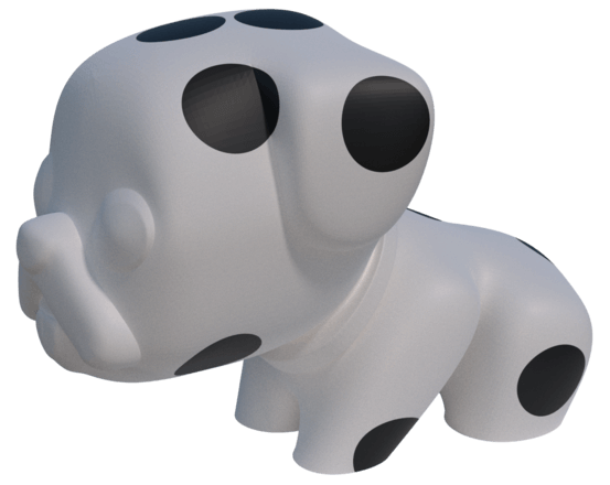
In this tutorial I’m going to cover how you can create your first, fully printable 3D printer file – a simple toy dog that can be 3D printed using relatively little support. This will introduce you to the idea of subdivision modelling, which is a way of making organic shapes, using a simple control mesh.

Here’s the a 2D template we’re going to use to design our model. It’s always wise to start with either an image or a sketch resembling what you want your finished model to look like.
For this how to make 3d printer files tutorial, we’ll be using the popular Blender design software for 3D printing as it is powerful, professional and free. It’s a great tool to get started to design for 3d printing while powerful enough to use for more complex designs as your skills grow.
Blender can seem very intimidating at first and I will try to keep the number of concepts quite simple. I am writing this for a complete Blender 3D printing novice and so I will cover some of the basic keyboard controls as I go.
The beauty of sub division modelling though is that you can achieve a lot using basic modelling steps like moving vertices, or extruding faces.
More experienced users may see easier ways of doing certain steps, but the focus of this how to design for 3D printing tutorial is to minimise the number of new tools that need to be introduced.
The main difference when you Learn 3d modelling for printing and more general 3D modelling is that you need to remember the physicality of the printed object. This means no holes, no loose pieces, no overlapping or intersecting surfaces.
If you make a point of fixing these issues throughout the modelling process then, by the end, you shouldn’t have much or anything that needs fixing.
It is very useful to use a 3 button mouse for Blender. You can get away with a two button mouse, but it’s inconvenient. For this CAD design for 3d printing tutorial I will assume you are using a 3 button mouse with a scroll wheel.
I have added a cheat sheet with the keypad and button presses at the bottom of the article. Why not save it, or print it off to always have it to hand.
Finally always remember to save your work regularly!
Getting Started 3D Printing With Blender
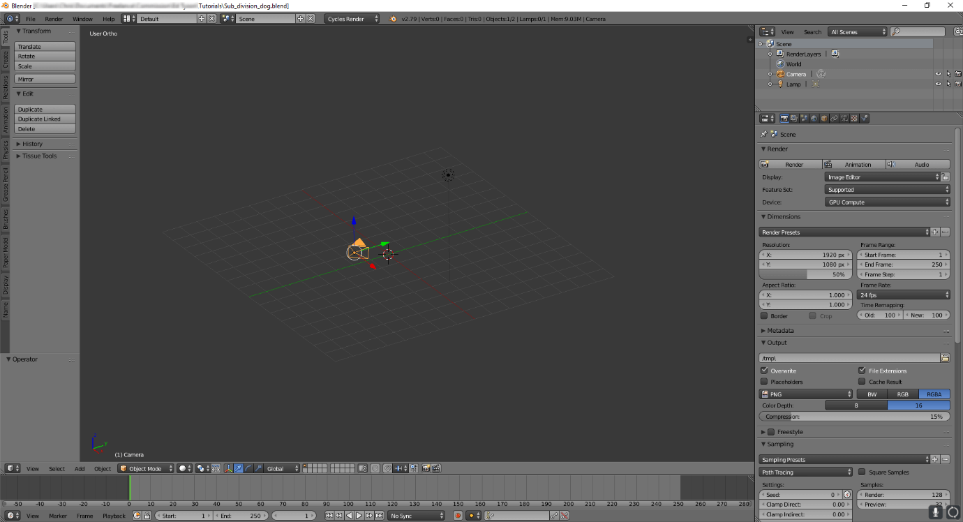
When you open Blender you should start with a scene looking a little like this. The big window in the middle is called the viewport. The bar on the left is called the Toolbar. You can ignore the right hand side for now. By holding down the middle mouse button you can rotate around the scene, and using the scroll wheel to zoom in and out.
If you have a cube in the middle, select it by clicking the right mouse button. It should have a yellow outline when selected. Then hit X and press delete in the pop up menu.
Make sure the 3D cursor (round thing with arrows) is in the middle of the ‘world’ by pressing Shift-C. The 3D cursor is also positioned by left clicking the mouse, so be aware of where the 3D cursor is for the following steps.
Beginning The Model
The next step is to make another cube! You do this by using the toolbar on the left (press T if it’s not open). Click on the ‘Create’ tab and select ‘Cube’. Down below you should get a ‘Add Cube’ menu. We are going to set the size by changing the radius to 50.
It’s important to be aware of the scale that you’re modelling at, and in this case 1 blender unit equals one mm. In this case we are going to make the dog about 10cm high.
The next step is to prepare any reference images that you want to use. I chose a cartoony dog picture I found on Wikipedia.
A 2D picture is just for reference only and it is very unlikely that you can find 2D pictures with the right qualities that will let you simply ‘trace’ it into 3D.
If you can’t find the image you would want to base your model on, take a moment to sketch out the design on some paper first. It will help especially while you learn cad for 3D printing.
You need to prepare the viewport for viewing the background image. First ensure that the viewport is in orthogonal view. This will make the grid lines nice and parallel like the above image.
You toggle between perspective and orthogonal view by pressing 5 on the numpad. Next change it to the front view by pressing 1 on the numpad.
To open up an image in the background you need to press ‘N’ which will open up a new toolbar on the right hand side of the viewport. Scroll down and tick ‘Background Images’.
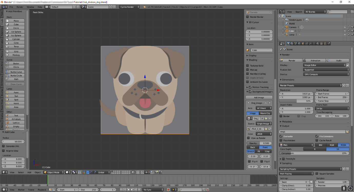
Add the image and select ‘Front’ to bring the image in front of the cube. You then need to scale and position the image. Blender doesn’t make this obvious but you should use the sliders above ‘Flip H’ and ‘Flip V’ to move the image up/down and side to side. To scale the image up, you use the slider below ‘Flip V’. To avoid the image popping up in other views change ‘All Views’ to ‘Front’.
You want to scale and position the image so that it is a suitable size for the job. This is why we made the cube first.
The next step is to begin shaping the cube. Enter edit mode by pressing ‘Tab’ on the keyboard. Select ‘edge select’ on the bar at the bottom. Press ‘Z’ to go into wireframe mode. Then select the horizontal bars. Press ‘W’ and you will get the menu like this.
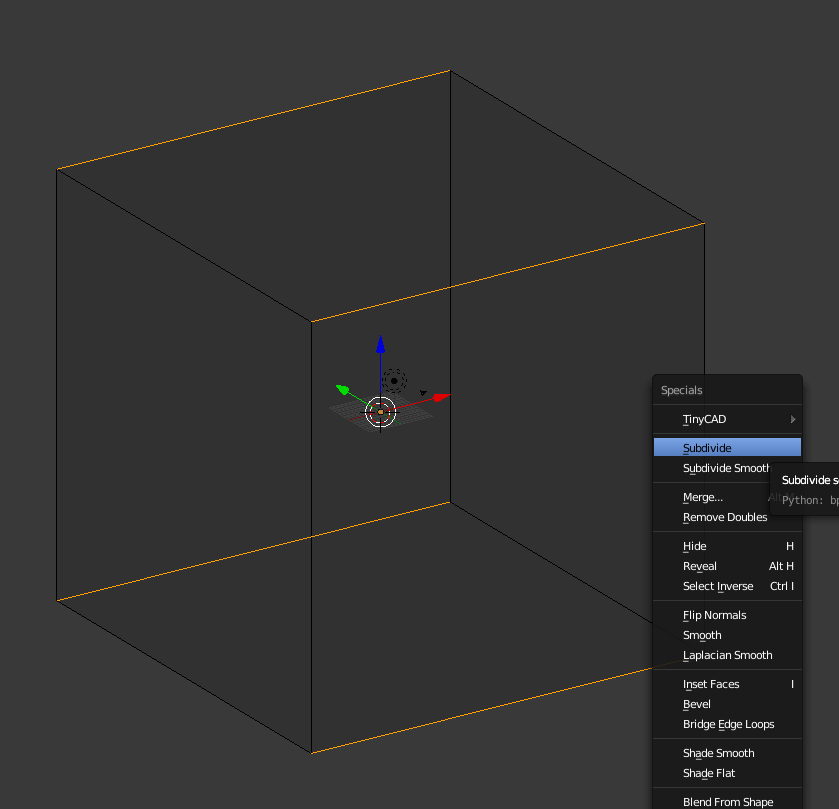
Select subdivide, which will add a ring of edges around the middle of the cube. Go to ‘vertex select’. Press ‘A’ to deselect all. Then press ‘B’ to enable box select. Use the left mouse button to select the vertices on the left hand side. Then delete them using the ‘X’ key. You should be left with the right and middle set of vertices. If you tab out of edit mode and press ‘Z’ to get out of wireframe mode you will see a hole in the side of the cube.
The next step is mirroring the model. This means that a change on one side is automatically applied to the other. Now is the time to look at the menus on the right. In the row of little icons you want to find the wrench icon. Click it and you are in the modifiers tab. Modifiers allow you to change the model without changing the geometry in edit mode. You can think of them as temporary modelling steps which you can turn off easily.
A modifier is turned into real geometry if you click ‘Apply’ so you don’t want to do that. If you do click it by accident you can undo it by pressing ‘Ctrl-Z’.
Select ‘Add modifier’ and then click ‘Mirror’. Make sure the x axis is the one selected and that merge is also selected. Merge means that the open edges will be ‘glued’ together and be seen as connected by any other modifiers you use.
Now we get to the subdivision step and start turning this cube into something dog like.
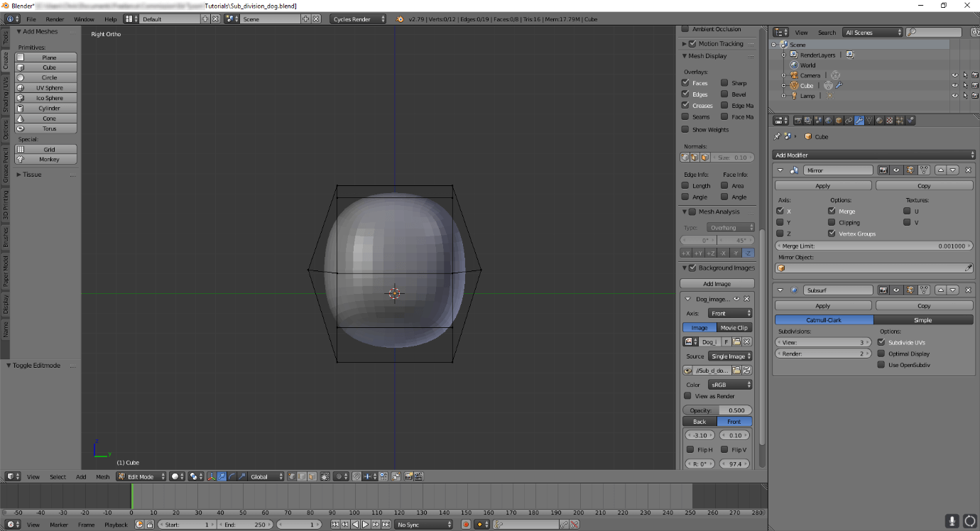
Without applying the mirror modifier select ‘Add modifier’ again. As long as ‘Catmull-Clark’ is selected you will see that the cube has become more rounded. If you increase the number in the ‘view’ slider you will see the cube become rounder and smoother as you increase the numbers. Right now a value of 3 or 4 is good enough.
Tab into edit mode and you will see the same edges as before like a cage around one half of the rounded cube. Now select the vertical edges again, like you did with the vertical ones. Subdivide them so that there is a ring running horizontally. Go to front view by pressing 1 on the numberpad again.
Now the fun begins.
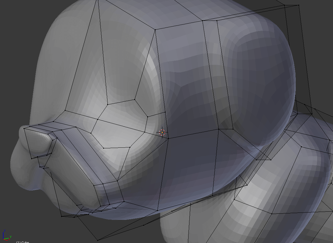
Click on a vertex by right clicking on it. Press ‘G’ and wriggle the mouse. You will see that it distorts the solid ball underneath. Move the vertices so that the rounded ball starts to match the rough shape of the dogs head. You can use the wireframe mode to select more than one vertex at a time. Press ‘3’ on the numpad to go into the side view and shape it so it’s roughly what you think the side of the dogs head will look like. You should get something like this.
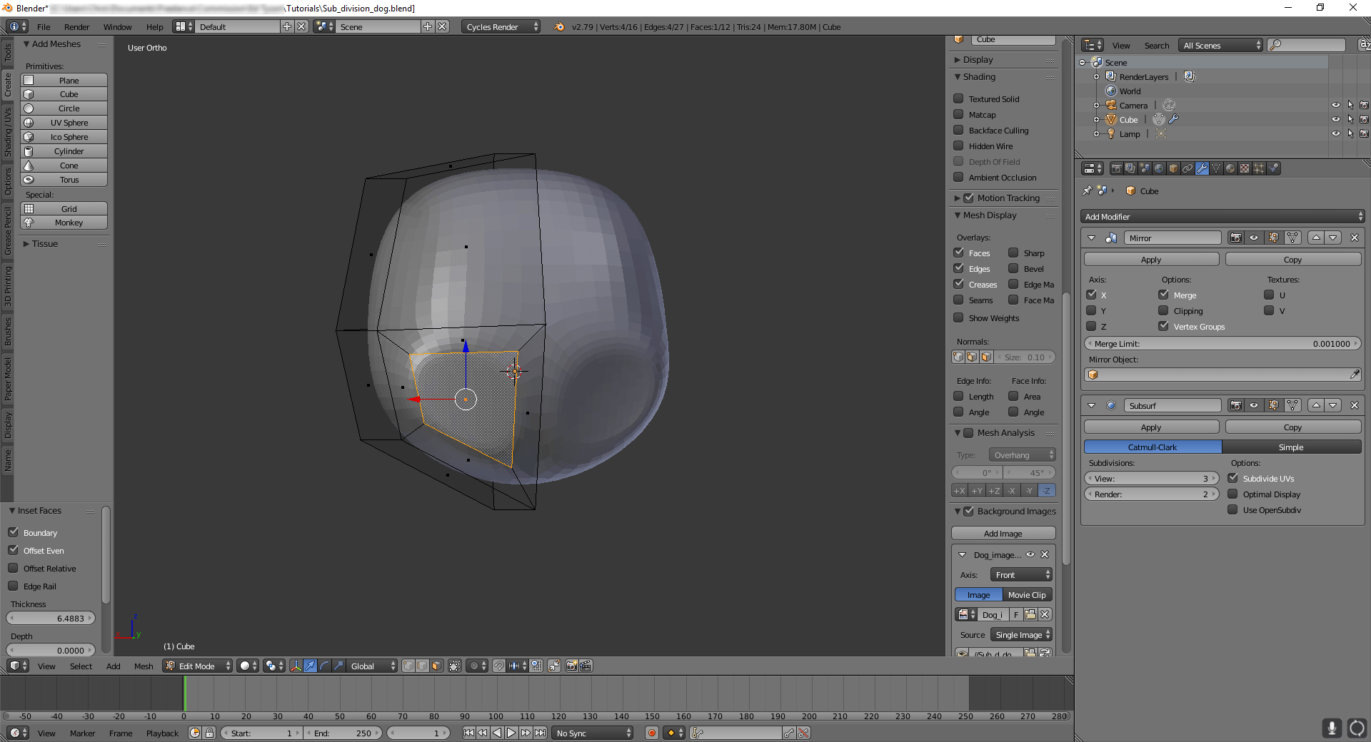
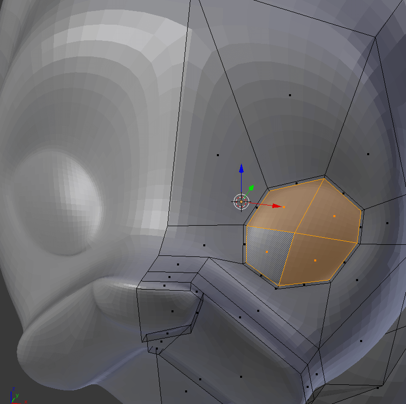
The next step will be to start creating the rough shape of the dog. Select the bottom left quad (four sided shape). Press ‘I’ and move the mouse.
You should see a smaller quad form within the larger one. Make it slightly smaller than the main one and click to save the change. You should see 2 patches on the rounded solid ball now.
You now want to make that indented face touch its mirror.
To do that you need to select the new face that connects to the mirror line and delete it. This leaves a hole in the rounded ball, but this is easy to fix. Select the 3D cursor option in the list below.
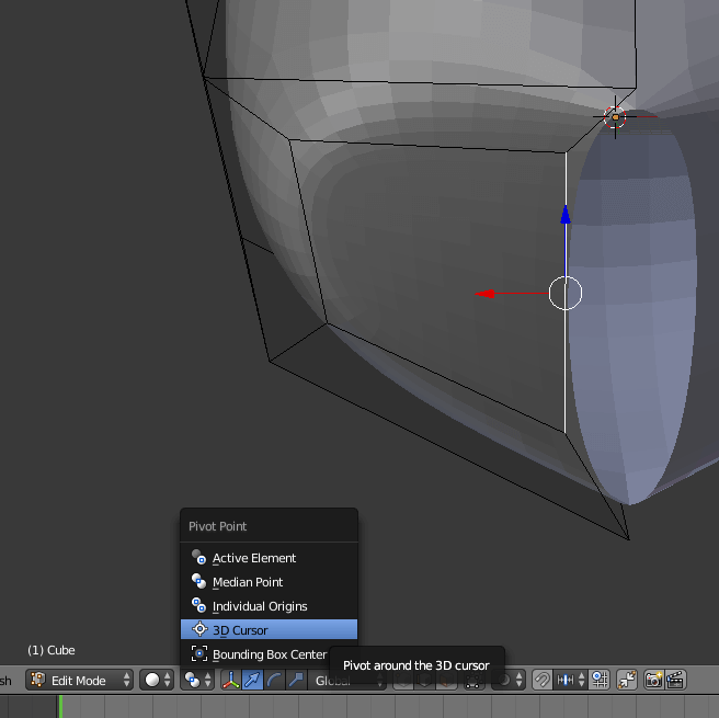
Make sure the 3D cursor is in the centre by clicking ‘Shift-C’. With the exposed edge selected press S to turn on scaling, then X to constrain the movement to the X dimension and then finally O to make them match the X position of the 3D cursor. The hole will now be closed.
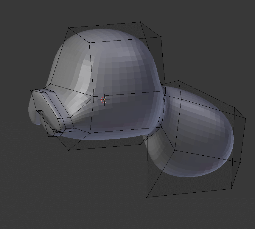
You can now move the vertices around to start shaping the muzzle. Repeat the same step on the other side of the head to start shaping the neck and body.

The final new tool to add in this tutorial is the cut tool. The cut tool will allow you to cut new edges in the faces of the model. First you press ‘K’ to activate the cut tool. It will snap to edges and vertices if you place them close enough. You can also chain cuts together to make edges and they are made permanent by pressing ‘Enter’.
Look at the front end and use the cutting tool to cut the upturned V of the mouth. Using the indent process to pull out the features until you get something like below.
You can now use cut to create the eyes. In front view trace out the eye on the model. The Subdivided model underneath will likely act weird during this step and look like it’s twisting up around the eye area. This can be fixed by adding a few additional cuts from the eye edge vertices to the vertices of the surrounding face like so.
This image also contains work on the ear and legs, which is achieved using the same cut, indent and move method as the mouth, except pulled out sideways.
Cut from the top of the eye, though the middle line and to the bottom. Select the 4 resulting faces and indent. This will give you the edge of the eye.
Move the vertices to give it a more organic shape.
To create the collar, select the ring around the neck and indent and pull it out. Clean it up like the previous mouth/neck and body steps, so that it forms a complete ring.
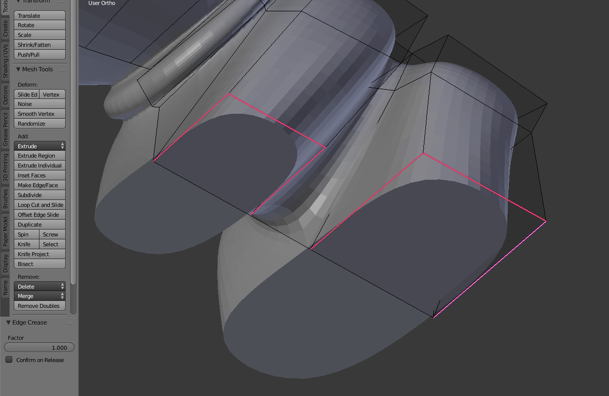
The next step is to add control to the amount of curvature on the edges. To do this you need to add a crease value to the edges. Select the edges of the feet like below and press shift-E and then left click with the mouse. On the left side below the tool menu you will see the ‘Edge crease’ options. Move the slider until you get the affect you want.
In this case you want a sharp edge. This will help with printing as well as stay in the simple/cartoony aesthetics of the toy.
You should also use this opportunity to make sure the fleet are flat. To do this select the faces that make up the bottom of the feet and then left click to put the 3D cursor where you want the feet flattened to. Press S to turn on scale, then Z to select the vertical axis, then press 0 to flatten them.
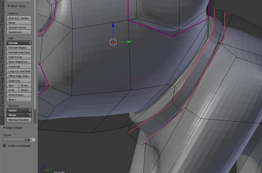
You can apply creasing to other edges such as the collar, eyes and ears to help shape them.
Using the tools you have learned now you can add features like the mouth and tongue as well as split the dogs legs into individual feet.
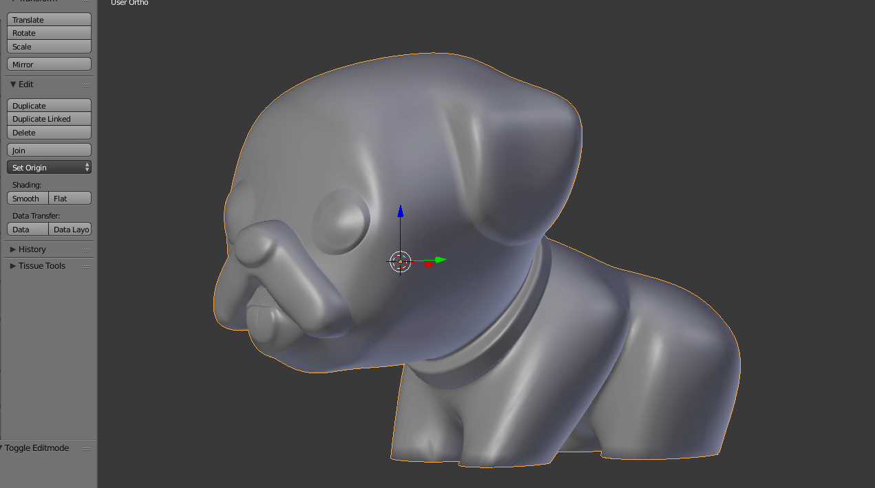
You can also use the smooth shading option to see what it will look like smoothed out. To do this tab out of edit mode and in the ‘Tools’ tab in the toolbar select ‘Smooth’ under shading. Note that this doesn’t look right around very sharp edges, e.g. the feet.
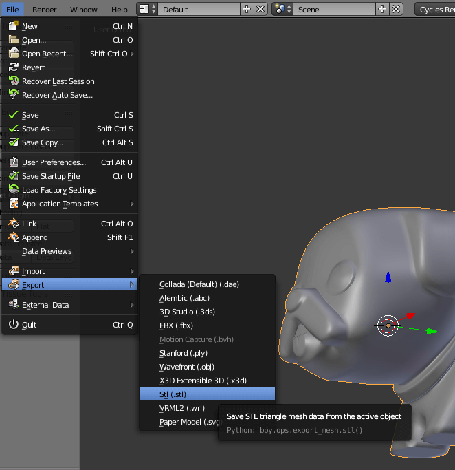
The next step is to export it in a printable format. Click File > Export > STL.
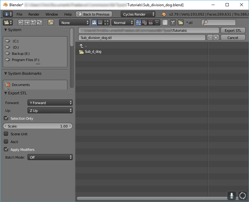
You will be shown the following screen. Ensure that ‘Selection only’ and ‘Apply modifiers’ are activated.
Now you have learned how to design something for 3D printing and have your own 3D printable STL file, a printable dog that’s ready to print!
If you’ve enjoyed this 3D printing design tutorial, subscribe to get updated on new guides and tutorials. We’ll take you on our journey to learn how to create 3D models for printing, so you can continue to improve your skill level.
3D Printing Design Tips:
- Supports are generally set to be applied on surfaces at 45 degree angles to the ground. If you can get away with an angle of 46 or more then you can print without using support.
- If you do need to support a surface, then make it easier to clean up/sand afterwards by avoiding details. g. The underside of the dogs head will need support, but is large and flat and so support removal will be easy.
- Use flat ground regions that can directly attach to the base. E.g. on the feet.
- A slight overhang on the edge of the ground regions can make it easier to remove, by allowing a blade to get under the print.
- Add more subdivision layers in order to get a smoother print. The number of triangles increases exponentially so don’t add too many layers.
- Subdivided models behave more predictably if the base mesh is composed of quads. If the mesh is folding over itself, it’s usually due to complex faces. Cut the faces into simpler quads to clean up the subdivided model.
- Every quad face on the base mesh will be subdivided into the same number of faces. So if an area of the model is still too triangular then subdivide or cut the base mesh for it.
- If you don’t want your final model symmetrical, try to do as much work prior to clicking apply on the mirror modifier. Any changes that could have been made before clicking apply will need to be done to both sides afterwards, and potentially doubling the total amount of work done.
Blender Mini Cheat Sheet:
Button/Key press | Function |
Right mouse button (RMB) | Select |
Middle mouse button press and hold | Rotate around the scene |
Left mouse button (LMB) | Position 3D cursor |
T | Toggle toolbar |
N | Toggle properties bar |
Tab | Toggle edit mode |
Z | Toggle Wireframe mode |
G | Move item around, in object or edit mode |
G then X,Y or Z | Move item but constrain to selected axis |
G then Shift-X,Y or Z | Move item but prevent movement on selected axis |
Shift-C | Centre 3d cursor on co-ordinates 0,0,0 |
I | Indent selected faces as one. |
I then I again | Indent selected faces as individuals. |
A | Toggle select all. |
S | Scale in object and edit mode. Scales relative to options: Active, Medium, 3D cursor etc |
S then X,Y or Z | Scale in selected axis. |
S then Shift-X,Y or Z | Scale in all but selected axis. |
Shift-C | Crease Edge |
K | Starts the cut tool. Left click to start the cut and left click to add a new cut vertex. Press enter to ok the cut. |
W | Specials menu, where you can access the editor subdivide tool. |
References:
https://upload.wikimedia.org/wikipedia/commons/d/db/Emojione_1F415.svg